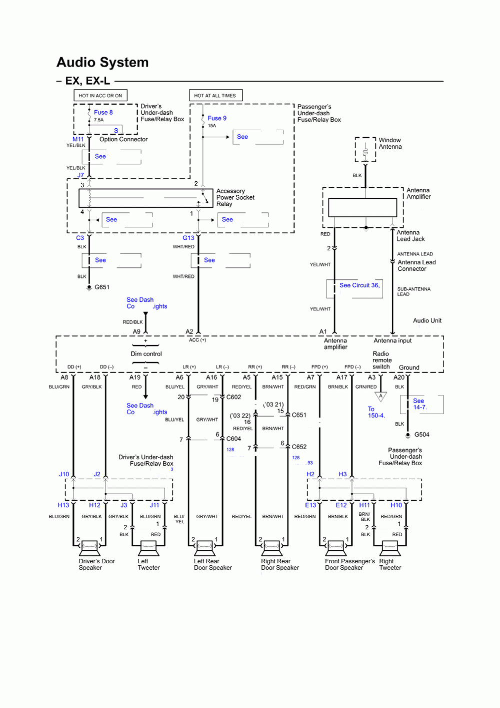
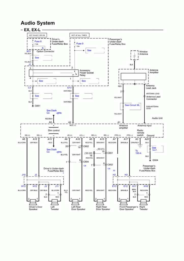
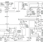
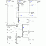
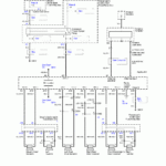
Wiring Diagram For A Radio In A 2004 Honda Pilot – The correct wiring diagram can help you to link up your vehicle. You can find 3 types to select from. Each kind does have its disadvantages and advantages. Be sure the wiring diagram you choose has right information. These are merely a couple of good examples: A13 is made for driving extras, and A23 for sub-insight. A more heavy weight might be maintained by fuller cables.
There are numerous options for attaching the remote on the cable
You have to be knowledgeable about the right way in order to connect the start up cable of any handheld remote control radio whenever you change it. This will likely avoid unwanted recent from depleting your battery. Seeking the fuse and appropriate wire is the first step. To achieve this, you should evaluate the fuse pack and guidebook. A fuse package electrical wiring diagram is another great idea.
The manufacturer go unit’s remote device wire is usually coupled to the power antenna cord. This electrical wiring solution can be useful whenever a radio station is not switched off after it is not employed. You may also connect the remote turn-on cable for the fuse package production terminal. This can be sure that the radio wire is just operated up as soon as the vehicle goes.
It is important to be familiar with the connector cable connections applied. The radio station cabling diagram ought to present the function and connections of each and every wire. A wiring diagram is wonderful for attaching the radio to the vehicle’s electric provide. It can also be utilized to change automobile stereos.
There are several approaches to link up the amplifier’s far off turn-on cable. First is to get in touch the amplifier’s remote control turn-on wire to some continuous power source. Alternately, you could use a swap or possibly a remote control to change about the amplifier personally. This will drain your battery if it isn’t in use.
Confirmation of your precision of wiring diagrams
Check the symbols. Auto electrical wiring diagrams can often use signs to determine a specific component. These icons can be quite a fuse, circuit circuit breaker, or fusible link. These diagrams will likely include connector symbols and manufacturer figures. You can be assured the wires diagrams you get are exact.
Following, authenticate the voltage. A DMM enables you to check the voltage. For weightier lots, thicker wire connections will likely be used. Also, check the voltage at A23. Increased voltage will likely be maintained by the lengthier cable. You can proceed to the next step if the voltage is correct.
