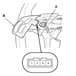
Wiring Diagram For Steering Wheel Radio Controls Honda Odyssey 2006 – The right wiring diagram can help you to hook up your automobile. You can find three types from which to choose. Each kind have their advantages and disadvantages. Ensure that the cabling diagram you decide on has right information. These are simply a number of examples: A13 is made for powering add-ons, and A23 for sub-enter. A bulkier load might be maintained by fuller cables.
There are several selections for attaching the remote for the cable
You ought to be informed about the correct way to connect the activate wire of the remote device radio station once you change it. This can protect against undesirable current from draining your electric battery. Picking out the fuse and suitable wire is the first task. To achieve this, you should look at the fuse container and manual. A fuse container cabling diagram can be another good idea.
The production line head unit’s handheld remote control wire is often coupled to the power antenna cable television. This wires alternative may be helpful when a fm radio is not really turned off after it is not used. You may also hook up the far off change-on cable for the fuse box output terminal. This can be sure that the fm radio wire is just driven up when the motor vehicle operates.
You should know about the connector cabling utilized. The fm radio electrical wiring diagram need to show the function and connections for each wire. A wires diagram is wonderful for attaching the radio for the vehicle’s electric powered supply. It may also be utilized to alter automobile stereos.
There are lots of strategies to hook up the amplifier’s remote control change-on wire. The very first is in order to connect the amplifier’s remote control change-on cable to some continuous source of energy. Alternately, you could use a change or a handheld control to make on the amplifier by hand. If it isn’t in use, this will drain your battery.
Confirmation of the accuracy of wires diagrams
Look at the symbols. Automotive wires diagrams may often use icons to identify a specific element. These signs can be a fuse, circuit circuit breaker, or fusible relationship. These diagrams may also contain connector manufacturer and symbols amounts. You can be certain that the electrical wiring diagrams you purchase are correct.
Next, verify the voltage. A DMM can be used to check the voltage. For heavier plenty, heavier wire connections will be employed. Also, look into the voltage at A23. Better voltage will likely be taken through the longer cable. You can proceed to the next step if the voltage is correct.
