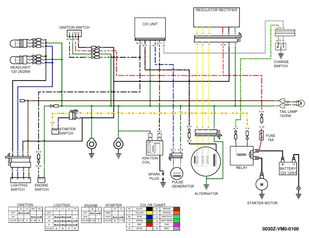
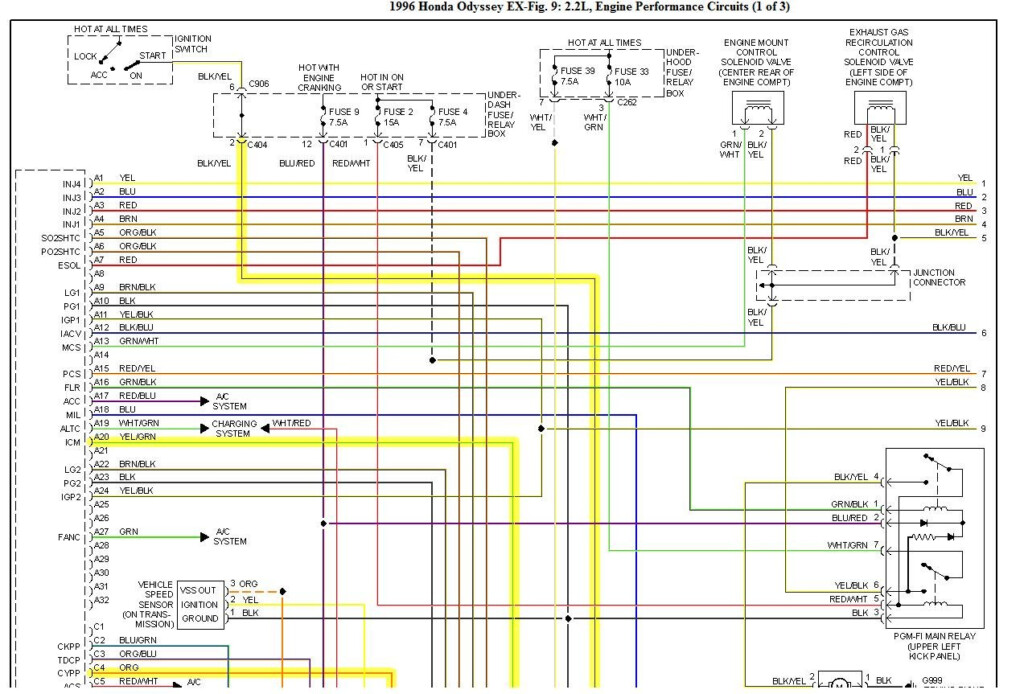
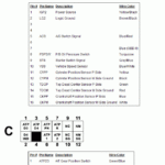
2009 Honda Odyssey Radio Wiring Diagram – The correct electrical wiring diagram can help you to link up your car. There are actually 3 varieties from which to choose. Each type does have its advantages and disadvantages. Ensure that the wires diagram you pick out has correct information. These are merely several examples: A13 is designed for driving add-ons, and A23 for sub-input. A more heavy load might be carried by fuller wires.
There are numerous alternatives for hooking up the distant to the cable
You ought to be informed about the proper way in order to connect the switch on wire of your remote device fm radio if you alter it. This will likely protect against undesirable present from emptying your battery. Choosing the fuse and appropriate cable is the initial step. To do this, it is very important assess the fuse box and guidebook. A fuse package cabling diagram can be another great idea.
The production line go unit’s remote control cable is usually linked to the energy antenna cable. This electrical wiring solution may be helpful each time a fm radio is not really switched off when it is not employed. Also you can connect the distant turn-on cable on the fuse container production terminal. This may ensure that the radio station cable is just driven up if the motor vehicle operates.
You should know about the connector wires used. The fm radio electrical wiring diagram must display the connections and function of each cable. A cabling diagram is wonderful for attaching the fm radio on the vehicle’s power provide. It can also be used to change car stereos.
There are several methods to connect the amplifier’s remote control convert-on cable. First is in order to connect the amplifier’s far off change-on wire into a continual source of energy. Alternately, you could use a switch or a remote device to transform on the amplifier by hand. This will drain your battery if it isn’t in use.
Affirmation of the accuracy and reliability of wires diagrams
Look into the emblems. Automotive wiring diagrams may often use signs to recognize a specific component. These emblems could be a fuse, circuit circuit breaker, or fusible interconnection. These diagrams will even have connector manufacturer and symbols numbers. You can be assured the wiring diagrams you buy are precise.
Next, authenticate the voltage. A DMM can be used to examine the voltage. For weightier lots, thicker cords will likely be applied. Also, look at the voltage at A23. Better voltage is going to be taken through the for a longer time wire. If the voltage is correct, you can proceed to the next step.

