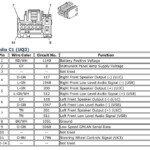
98 Honda Crv Radio Wiring Diagram – The proper wiring diagram can make it easier to link up your vehicle. You will find a few varieties to select from. Each kind have their advantages and disadvantages. Ensure the cabling diagram you pick out has correct details. These are simply several examples: A13 is made for driving components, and A23 for sub-input. A heavier fill might be taken by heavier wire connections.
There are numerous selections for hooking up the remote towards the cable
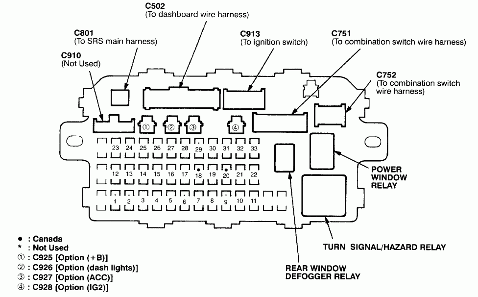
You should be familiar with the correct way to get in touch the turn on wire of any remote device radio station whenever you adjust it. This can avoid unwanted recent from draining your electric battery. Seeking the fuse and appropriate wire is the first task. To accomplish this, you should review the fuse package and guidebook. A fuse container electrical wiring diagram can be another great idea.
The manufacturer mind unit’s handheld control wire is frequently connected to the potential antenna cable tv. This electrical wiring option can be beneficial when a radio station is not really turned off after it is not applied. You can also link up the remote transform-on wire for the fuse package production terminal. This may ensure that the radio cable is only powered up when the car runs.
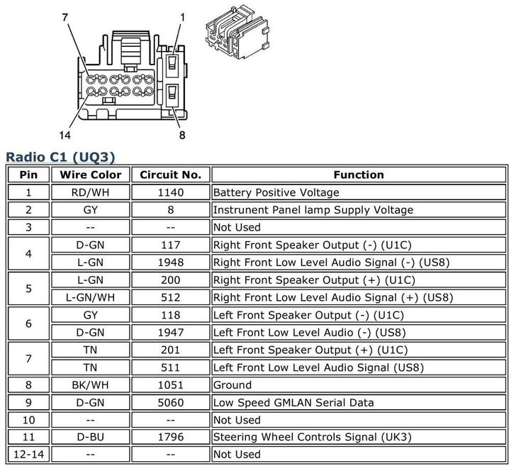
It is essential to be aware of the connector cable connections employed. The radio cabling diagram need to display the connections and function for each wire. A wires diagram is useful for connecting the fm radio for the vehicle’s electric supply. It can also be used to modify automobile stereos.
There are many ways to hook up the amplifier’s remote convert-on wire. The initial one is in order to connect the amplifier’s remote control transform-on wire to a continuous power source. Alternately, you could utilize a switch or even a handheld remote control to turn on the amplifier physically. If it isn’t in use, this will drain your battery.
Affirmation from the reliability of cabling diagrams
Look into the signs. Automotive cabling diagrams may often use symbols to determine a selected element. These emblems can be a fuse, circuit circuit breaker, or fusible link. These diagrams may also include connector symbols and manufacturer phone numbers. You can be certain the electrical wiring diagrams you acquire are precise.
Following, authenticate the voltage. A DMM enables you to look at the voltage. For heavier loads, heavier wires will be employed. Also, look at the voltage at A23. Better voltage will be carried by the lengthier cable. If the voltage is correct, you can proceed to the next step.
