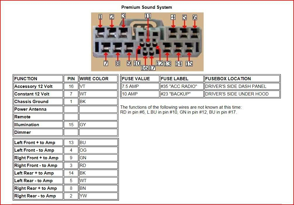
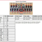
2006 Honda Accord Radio Wiring Diagram – The best wires diagram can help you to connect your car. There are three varieties from which to choose. Each kind has its own advantages and disadvantages. Ensure the cabling diagram you decide on has appropriate information and facts. These are merely a number of cases: A13 is designed for powering add-ons, and A23 for sub-insight. A bulkier fill might be taken by thicker wires.
There are numerous alternatives for connecting the remote towards the wire
You ought to be informed about the correct way to get in touch the switch on wire of the remote control fm radio when you change it. This will avoid undesirable present from depleting your battery power. Seeking the fuse and suitable cable is the first task. To achieve this, it is very important evaluate the fuse box and handbook. A fuse pack wiring diagram is another wise decision.
The manufacturing facility go unit’s remote control cable is often coupled to the potential antenna cord. This wires solution could be valuable every time a radio station will not be turned off when it is not being employed. You can also hook up the remote transform-on wire to the fuse box productivity terminal. This may be sure that the radio station wire is only powered up if the motor vehicle goes.
You should be aware of the connector cabling applied. The fm radio cabling diagram must show the function and connections of each wire. A cabling diagram is useful for connecting the radio to the vehicle’s electric source. It can also be utilized to transform car stereos.
There are lots of approaches to link the amplifier’s far off change-on cable. The initial one is to connect the amplifier’s distant convert-on wire to a continual source of energy. Alternately, you can use a swap or possibly a handheld remote control to change about the amplifier personally. This will drain your battery if it isn’t in use.
Verification from the precision of wires diagrams
Examine the symbols. Vehicle wires diagrams could use signs to distinguish a specific aspect. These emblems can be a fuse, circuit breaker, or fusible relationship. These diagrams will likely have connector manufacturer and symbols amounts. You can be certain how the wiring diagrams you acquire are correct.
Next, verify the voltage. A DMM may be used to examine the voltage. For bulkier lots, heavier cables will probably be used. Also, look into the voltage at A23. Increased voltage will probably be carried by the longer cable. If the voltage is correct, you can proceed to the next step.
