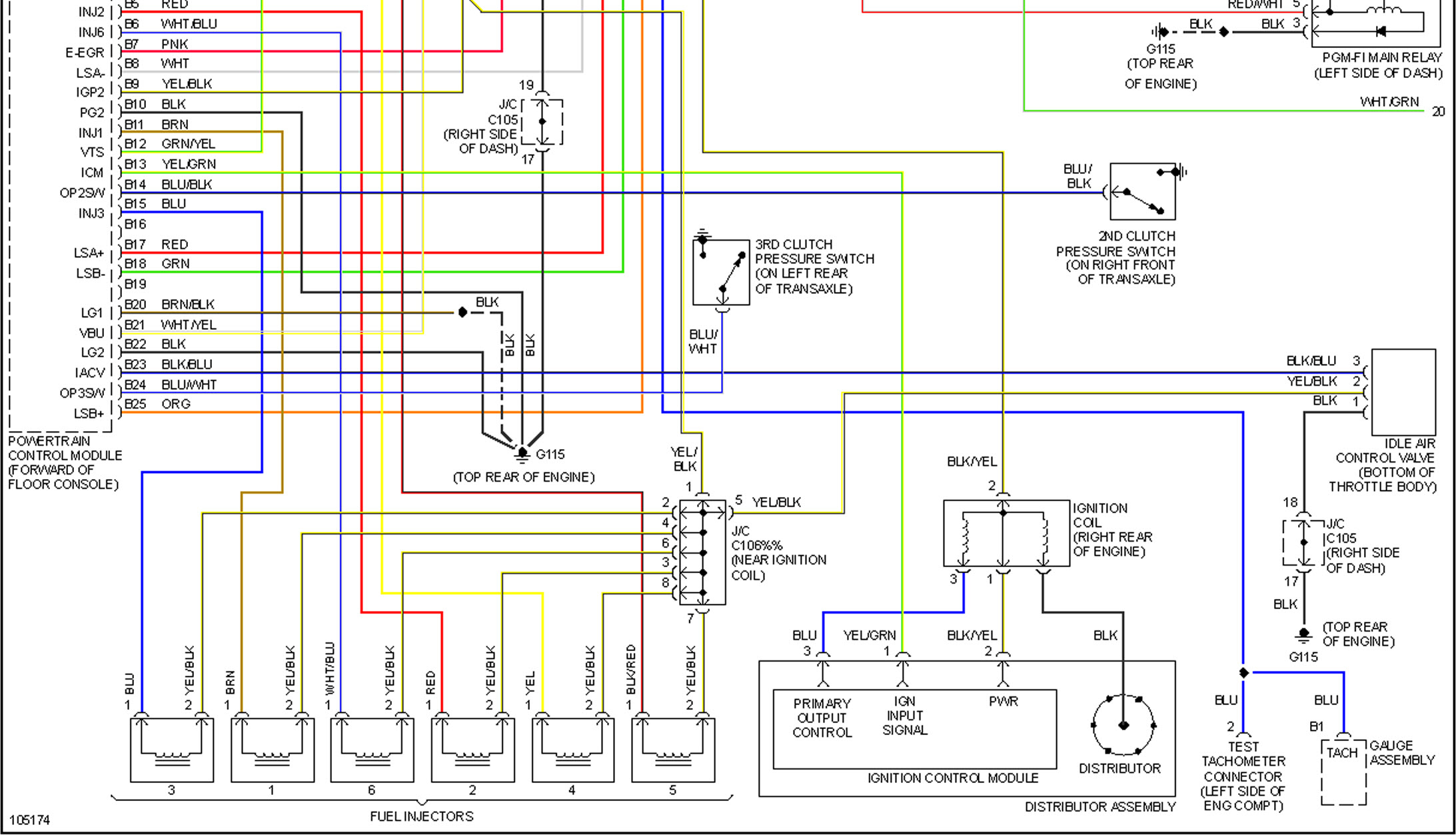
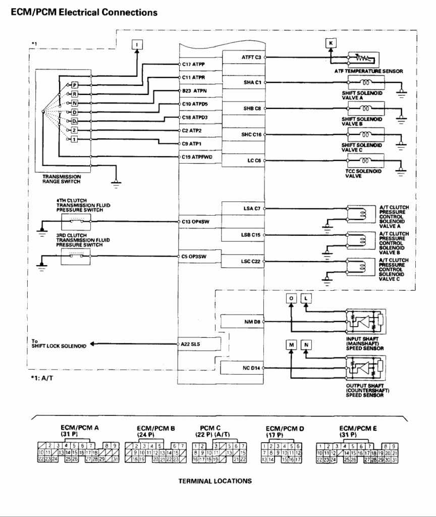
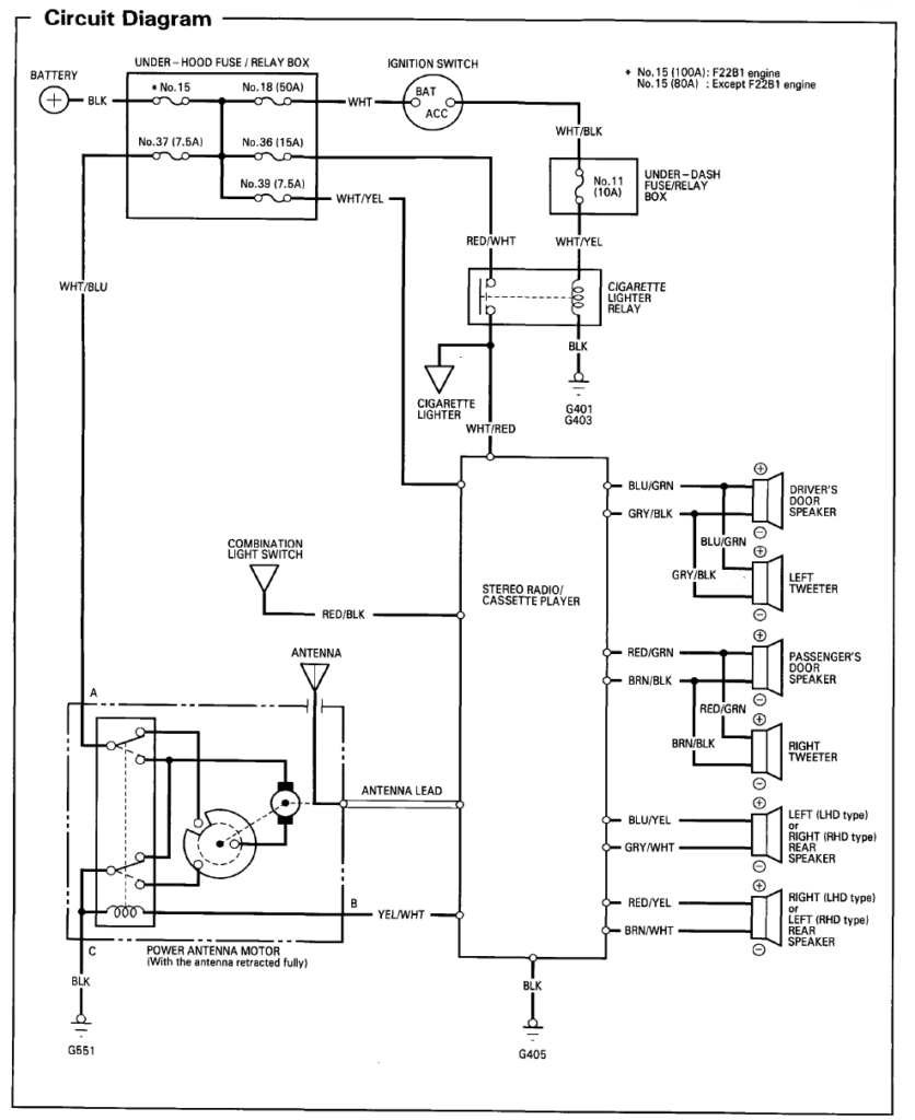
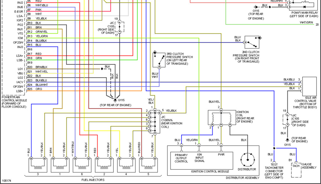
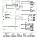
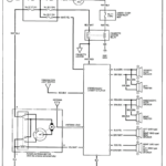
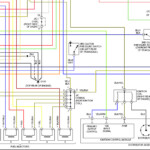
1995 Honda Accord Radio Wiring Diagram – The proper wiring diagram can help you to connect your automobile. There are actually about three varieties to select from. Every type has its disadvantages and advantages. Ensure the wiring diagram you pick out has appropriate details. These are merely a couple of illustrations: A13 is designed for running extras, and A23 for sub-enter. A bulkier stress may be taken by heavier cords.
There are many choices for hooking up the remote towards the cable
You ought to be acquainted with the proper way in order to connect the activate wire of the handheld control radio whenever you modify it. This may stop unwanted current from draining your battery power. Locating the fuse and suitable wire is the first step. To get this done, it is very important evaluate the fuse package and guidebook. A fuse box wires diagram is yet another wise decision.
The production line head unit’s handheld remote control wire is normally linked to the energy antenna cable. This wires choice could be helpful every time a radio is not turned off when it is not applied. You can also hook up the remote turn-on wire towards the fuse package productivity terminal. This can be sure that the fm radio wire is merely run up once the vehicle operates.
It is essential to know about the connector wires utilized. The radio station cabling diagram ought to demonstrate the connections and function of every wire. A wires diagram is wonderful for hooking up the radio station towards the vehicle’s electric offer. It could also be utilized to transform car stereos.
There are several ways to link the amplifier’s far off change-on cable. First is for connecting the amplifier’s far off change-on cable to your continuous power source. Alternately, you can use a move or even a remote device to turn in the amplifier physically. If it isn’t in use, this will drain your battery.
Confirmation of your accuracy and reliability of electrical wiring diagrams
Look at the symbols. Automotive electrical wiring diagrams can often use symbols to identify a selected component. These signs can be a fuse, circuit breaker, or fusible link. These diagrams may also include connector symbols and manufacturer phone numbers. You can be assured how the electrical wiring diagrams you acquire are correct.
After that, verify the voltage. A DMM can be used to look at the voltage. For heavier plenty, thicker wires will be used. Also, examine the voltage at A23. Increased voltage will likely be maintained from the much longer wire. If the voltage is correct, you can proceed to the next step.
