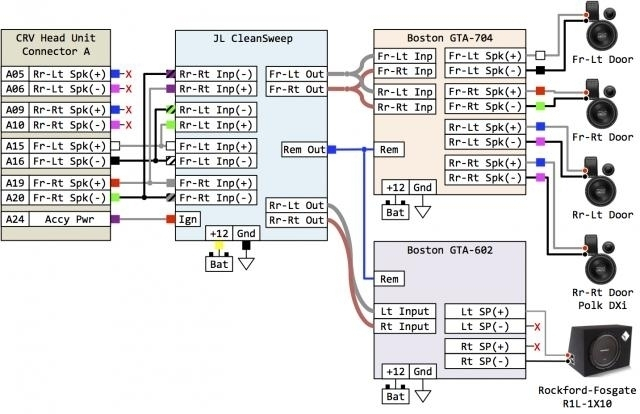
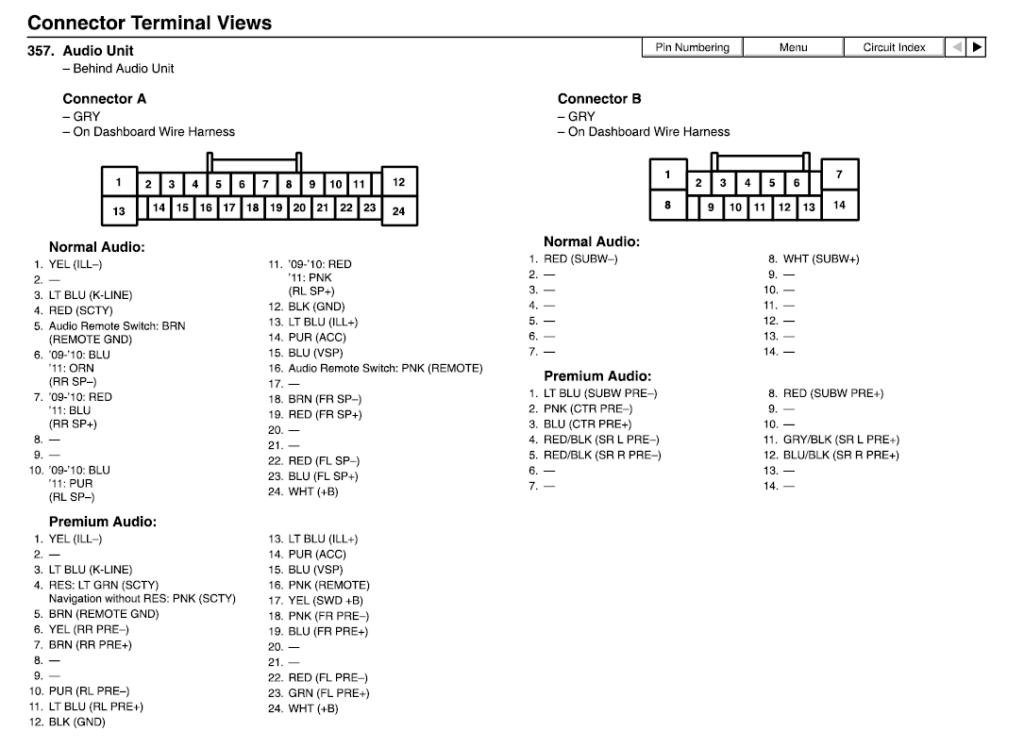
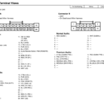
2009 Honda Pilot Radio Wiring Diagram – The best cabling diagram can help you to hook up your car or truck. There are actually a few types to choose from. Each type has its own disadvantages and advantages. Make sure the electrical wiring diagram you decide on has correct details. These are merely a few examples: A13 is made for running accessories, and A23 for sub-feedback. A bulkier load might be transported by heavier wires.
There are numerous selections for connecting the distant for the wire
You need to be informed about the correct way to get in touch the turn on wire of any remote device stereo once you alter it. This will avoid undesirable current from emptying your battery. Seeking the fuse and correct cable is step one. To accomplish this, you should look at the fuse box and guidebook. A fuse pack electrical wiring diagram is yet another good idea.
The factory head unit’s handheld remote control cable is frequently connected to the energy antenna cable television. This wiring option may be valuable every time a fm radio is not switched off after it is not employed. Also you can link up the distant turn-on wire towards the fuse pack output terminal. This may be sure that the radio wire is only operated up if the car operates.
You should be aware of the connector cables employed. The stereo electrical wiring diagram must demonstrate the connections and function of each and every wire. A electrical wiring diagram is wonderful for attaching the fm radio towards the vehicle’s electrical supply. It could also be utilized to alter car stereos.
There are many ways to link up the amplifier’s distant turn-on wire. The first is in order to connect the amplifier’s remote transform-on wire to your constant power source. Alternately, you could use a switch or perhaps a handheld remote control to make in the amplifier manually. If it isn’t in use, this will drain your battery.
Affirmation in the reliability of electrical wiring diagrams
Look at the signs. Auto wires diagrams can frequently use signs to recognize a selected part. These symbols can be a fuse, circuit breaker, or fusible relationship. These diagrams will also consist of connector symbols and manufacturer phone numbers. You can be certain the cabling diagrams you acquire are accurate.
Up coming, validate the voltage. A DMM could be used to look at the voltage. For more heavy lots, thicker wire connections will be utilized. Also, look at the voltage at A23. Higher voltage will be maintained through the longer wire. If the voltage is correct, you can proceed to the next step.
