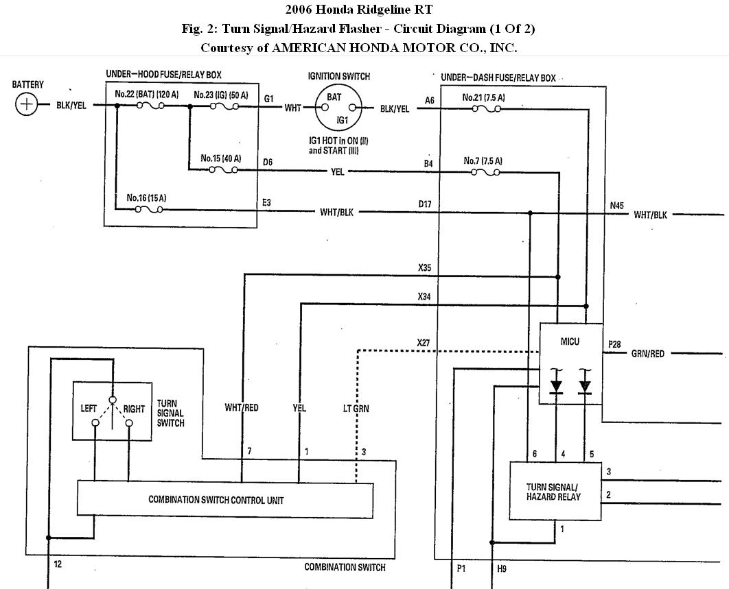
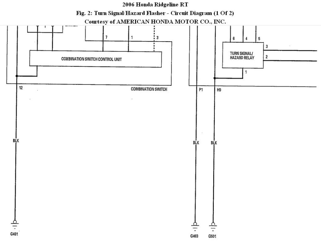
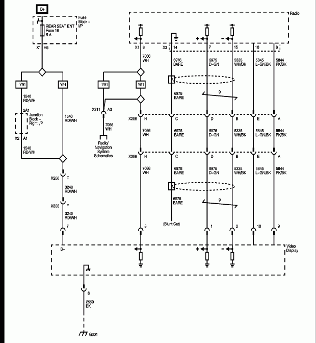
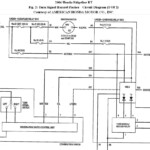
2007 Honda Ridgeline Radio Wiring Diagram – The right wires diagram can help you to connect your vehicle. You will find about three types to choose from. Every type has its advantages and disadvantages. Make sure the wiring diagram you choose has proper information and facts. These are just several good examples: A13 is perfect for powering accessories, and A23 for sub-feedback. A heavier load can be carried by heavier wires.
There are several alternatives for linking the remote control to the cable
You have to be knowledgeable about the proper way to connect the turn on wire of a remote control radio once you adjust it. This may prevent unwanted existing from draining your electric battery. Seeking the fuse and proper wire is the first task. To accomplish this, it is essential to evaluate the fuse package and handbook. A fuse container electrical wiring diagram can be another great idea.
The factory go unit’s remote device cable is frequently attached to the power antenna cable television. This electrical wiring option could be helpful each time a stereo will not be switched off when it is not utilized. You can even link the remote control change-on cable on the fuse pack result terminal. This will likely ensure that the stereo wire is merely driven up when the car operates.
It is important to be familiar with the connector cable connections utilized. The fm radio wiring diagram must show the connections and function of every cable. A wires diagram is wonderful for linking the radio to the vehicle’s electric provide. It can also be accustomed to alter auto stereos.
There are lots of approaches to link up the amplifier’s remote turn-on cable. First is for connecting the amplifier’s remote control convert-on wire to your frequent source of energy. Alternately, you could use a switch or even a handheld remote control to change in the amplifier manually. If it isn’t in use, this will drain your battery.
Verification from the accuracy and reliability of wiring diagrams
Examine the emblems. Vehicle cabling diagrams may often use icons to determine a selected part. These emblems can be a fuse, circuit circuit breaker, or fusible interconnection. These diagrams will likely consist of connector symbols and manufacturer amounts. You can be certain that this electrical wiring diagrams you acquire are accurate.
Next, verify the voltage. A DMM may be used to check the voltage. For heavier lots, thicker cords will be used. Also, examine the voltage at A23. Increased voltage will be maintained by the much longer cable. If the voltage is correct, you can proceed to the next step.
