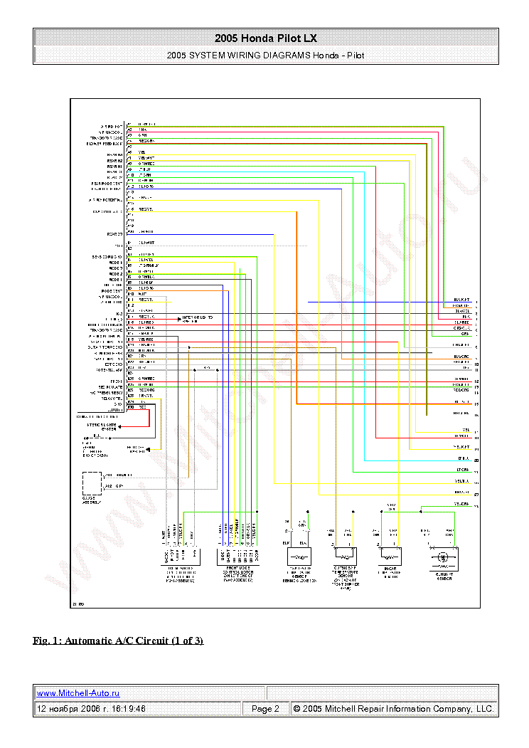
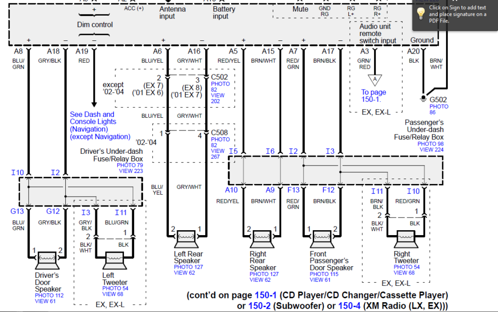
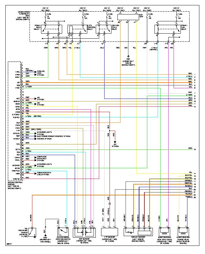
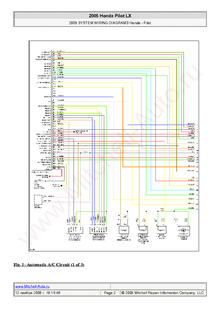
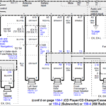
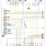
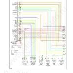
2004 Honda Odyssey Radio Wiring Diagram – The correct wires diagram can help you to connect your vehicle. You can find about three sorts from which to choose. Each type has its advantages and disadvantages. Be sure the wires diagram you pick out has correct information. These are just a number of examples: A13 is for powering add-ons, and A23 for sub-input. A bulkier stress can be transported by thicker cords.
There are numerous choices for linking the remote to the wire
You should be familiar with the correct way in order to connect the turn on cable of a remote device fm radio once you alter it. This can protect against unwanted current from emptying your battery. Picking out the fuse and appropriate cable is the first step. To do this, it is essential to evaluate the fuse pack and handbook. A fuse pack wiring diagram can be another great idea.
The factory go unit’s remote device cable is usually connected to the strength antenna cable television. This wiring option could be useful every time a radio will not be switched off when it is not being applied. Also you can hook up the far off turn-on wire for the fuse package result terminal. This can ensure that the radio station cable is only operated up when the vehicle runs.
It is essential to be familiar with the connector cabling employed. The radio station wires diagram need to demonstrate the function and connections for each cable. A cabling diagram is wonderful for hooking up the stereo to the vehicle’s electric provide. It is also used to change automobile stereos.
There are lots of ways to connect the amplifier’s distant turn-on cable. The first is to connect the amplifier’s remote transform-on wire into a continuous power source. Alternately, you could use a move or a remote control to transform around the amplifier physically. If it isn’t in use, this will drain your battery.
Confirmation in the reliability of wiring diagrams
Examine the emblems. Automotive cabling diagrams could use symbols to determine a specific part. These symbols can be quite a fuse, circuit circuit breaker, or fusible interconnection. These diagrams may also include connector symbols and manufacturer amounts. You can be assured that this cabling diagrams you acquire are exact.
Up coming, verify the voltage. A DMM enables you to examine the voltage. For heavier tons, heavier wire connections will likely be applied. Also, look into the voltage at A23. Higher voltage will be maintained by the for a longer time wire. If the voltage is correct, you can proceed to the next step.
