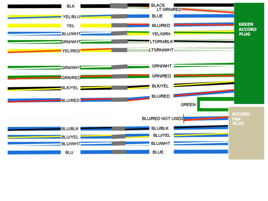
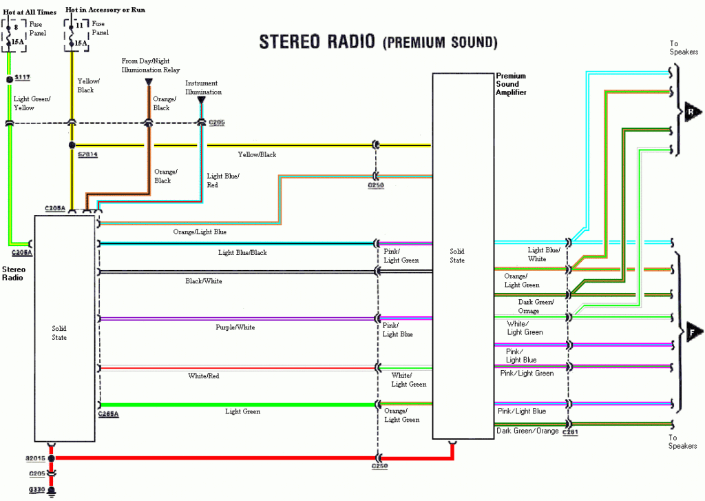
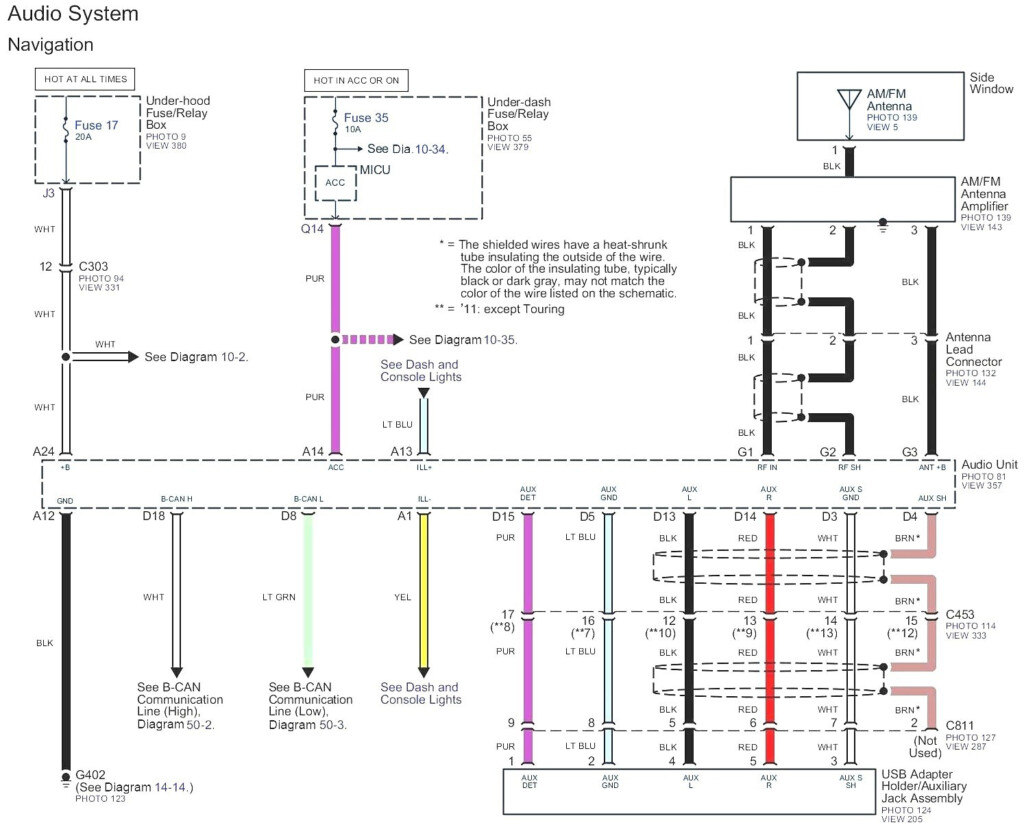
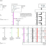
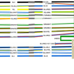
2000 Honda Accord Radio Wiring Diagram – The best electrical wiring diagram can help you to link up your car. You can find a few types from which to choose. Each type has its disadvantages and advantages. Be sure the wires diagram you select has proper information. These are just a few examples: A13 is perfect for powering accessories, and A23 for sub-input. A heavier load might be transported by fuller cords.
There are several options for connecting the distant for the cable
You need to be familiar with the proper way for connecting the start up cable of a handheld remote control radio once you alter it. This may stop unwelcome existing from draining your battery power. Choosing the fuse and suitable wire is step one. To accomplish this, it is essential to assess the fuse package and handbook. A fuse container electrical wiring diagram is another good idea.
The production line go unit’s remote control wire is frequently linked to the power antenna cord. This wiring choice could be helpful whenever a radio station is just not turned off after it is not being employed. You can also link up the remote control convert-on cable on the fuse pack production terminal. This will be sure that the radio wire is merely operated up as soon as the automobile works.
It is very important be familiar with the connector cable connections applied. The radio electrical wiring diagram should demonstrate the function and connections of each and every wire. A wiring diagram is wonderful for attaching the stereo towards the vehicle’s electric powered offer. It may also be employed to change automobile stereos.
There are lots of methods to link the amplifier’s far off convert-on cable. First is for connecting the amplifier’s remote convert-on wire into a frequent source of energy. Alternately, you could use a switch or possibly a remote device to turn about the amplifier physically. This will drain your battery if it isn’t in use.
Verification in the reliability of wires diagrams
Look into the icons. Automotive electrical wiring diagrams can often use signs to identify a specific component. These icons might be a fuse, circuit breaker, or fusible relationship. These diagrams will likely contain connector manufacturer and symbols figures. You can be assured the wiring diagrams you buy are precise.
Following, verify the voltage. A DMM enables you to examine the voltage. For more heavy lots, heavier cords will likely be used. Also, check the voltage at A23. Increased voltage will probably be maintained through the lengthier cable. You can proceed to the next step if the voltage is correct.
