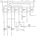
1997 Honda Passport Radio Wiring Diagram – The correct cabling diagram can make it easier to link up your car. You can find three varieties from which to choose. Every type has its advantages and disadvantages. Ensure the cabling diagram you choose has appropriate information. These are only a few examples: A13 is for running add-ons, and A23 for sub-input. A bulkier weight might be carried by heavier wire connections.
There are numerous alternatives for attaching the remote on the wire
You need to be acquainted with the right way to connect the turn on wire of your remote control radio station when you adjust it. This may prevent unwanted existing from emptying your battery power. Picking out the fuse and appropriate cable is the first task. To achieve this, it is important to evaluate the fuse box and manual. A fuse box wires diagram is also a wise decision.
The production line go unit’s handheld control cable is frequently attached to the potential antenna cable. This wires solution could be beneficial whenever a stereo will not be switched off when it is not utilized. You can even hook up the far off convert-on wire to the fuse box productivity terminal. This may ensure that the fm radio wire is simply run up as soon as the car runs.
It is essential to be aware of the connector cable connections utilized. The stereo cabling diagram ought to show the function and connections of each and every wire. A wires diagram is wonderful for connecting the radio station to the vehicle’s power supply. It can also be utilized to modify auto stereos.
There are several approaches to link the amplifier’s distant convert-on wire. The first is in order to connect the amplifier’s far off change-on cable to a continual power source. Alternately, you could use a move or possibly a remote device to turn about the amplifier by hand. If it isn’t in use, this will drain your battery.
Confirmation of your precision of wires diagrams
Check the symbols. Automotive cabling diagrams can often use symbols to identify a particular element. These symbols might be a fuse, circuit circuit breaker, or fusible link. These diagrams may also include connector symbols and manufacturer amounts. You can be assured the wires diagrams you buy are precise.
Following, verify the voltage. A DMM can be used to examine the voltage. For heavier tons, heavier cables will probably be applied. Also, look at the voltage at A23. Better voltage is going to be transported through the longer cable. You can proceed to the next step if the voltage is correct.
