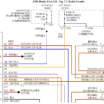
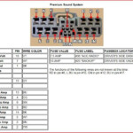
1993 Honda Civic Dx Radio Wiring Diagram – The correct cabling diagram can make it easier to link up your car. There are actually about three varieties from which to choose. Every type have their advantages and disadvantages. Ensure the cabling diagram you pick out has appropriate details. These are merely a few good examples: A13 is designed for driving components, and A23 for sub-insight. A weightier fill can be maintained by fuller cables.
There are many selections for attaching the remote control to the wire
You ought to be informed about the right way to get in touch the turn on wire of any remote control stereo when you alter it. This will prevent undesirable existing from draining your battery. Seeking the fuse and proper wire is the first step. To achieve this, you should look at the fuse container and guidebook. A fuse pack wiring diagram is yet another good idea.
The manufacturing facility head unit’s remote device wire is normally connected to the energy antenna cable. This electrical wiring choice might be beneficial when a fm radio is just not switched off when it is not used. You can even link the remote turn-on cable towards the fuse pack result terminal. This will be sure that the radio station cable is only driven up if the vehicle operates.
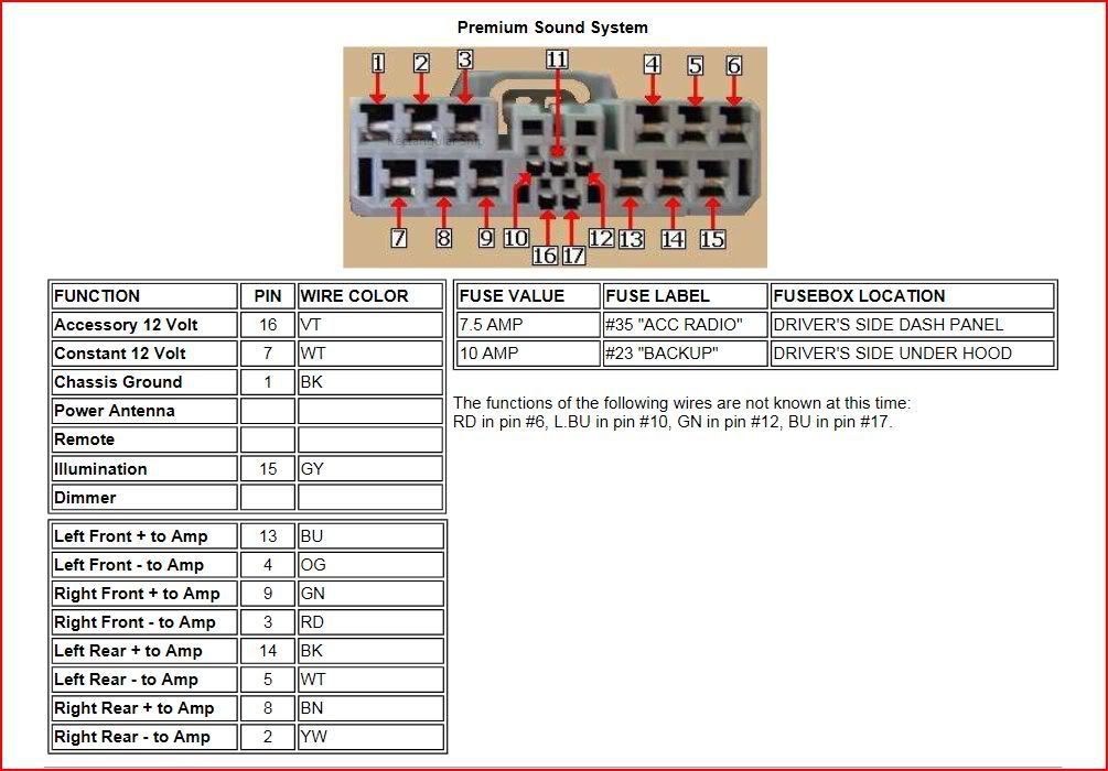
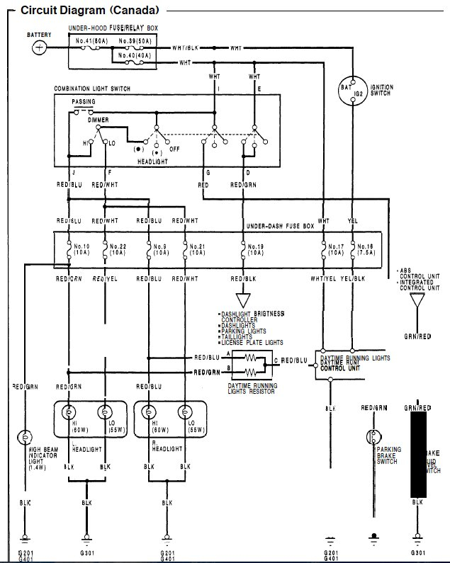
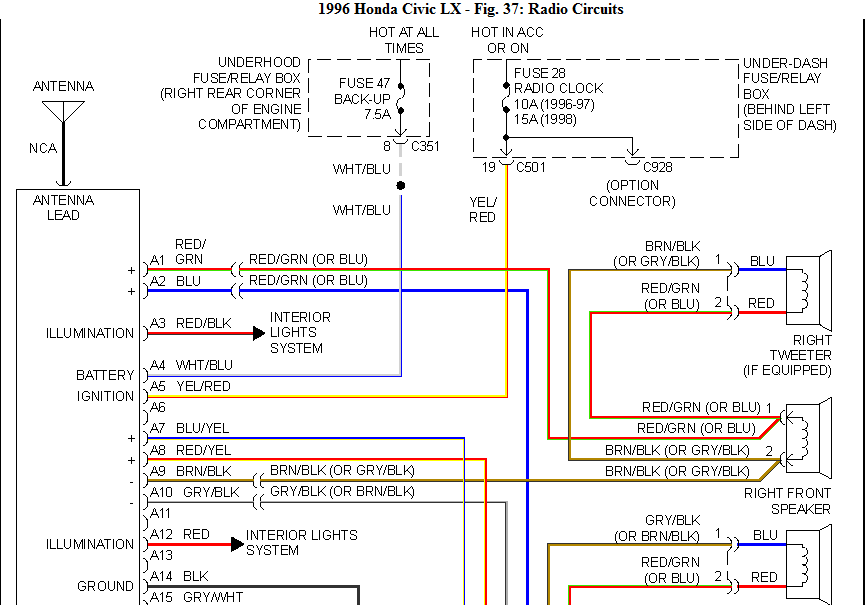
It is important to be familiar with the connector cable connections utilized. The fm radio wiring diagram must present the function and connections of every wire. A electrical wiring diagram is useful for hooking up the stereo for the vehicle’s electric powered offer. It can also be used to transform automobile stereos.
There are lots of strategies to hook up the amplifier’s remote convert-on cable. First is in order to connect the amplifier’s far off turn-on cable into a constant source of energy. Alternately, you could utilize a change or perhaps a handheld remote control to turn about the amplifier physically. If it isn’t in use, this will drain your battery.
Affirmation of your precision of wires diagrams
Check the signs. Automotive wiring diagrams can frequently use emblems to distinguish a selected part. These signs might be a fuse, circuit breaker, or fusible connection. These diagrams will likely have connector manufacturer and symbols numbers. You can be certain the electrical wiring diagrams you acquire are exact.
Next, confirm the voltage. A DMM can be used to check the voltage. For more heavy tons, thicker wires is going to be applied. Also, look into the voltage at A23. Increased voltage will likely be carried through the for a longer time wire. You can proceed to the next step if the voltage is correct.
